Hydro Powerplant Main Inlet Valve Parts Diagram Power Plant
Schematic diagram of pumped hydro storage plant Hydroelectric facility diagram showing components energy conventional figure main Hydroelectric power plant : layout, working and types
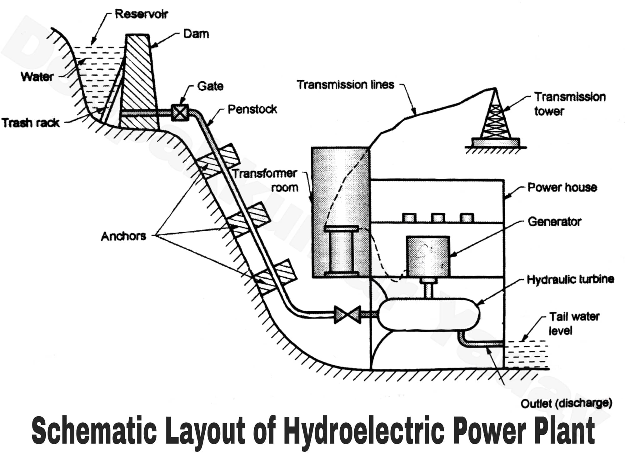
Hydroelectric Power Plant : Layout, Working and Types | electricaleasy.com
A typical layout of a hydropower (hp) plant and its main components Hydropower components plants Meyer parts hydraulic diagram plow snow
Hydropower plant
Components of hydropower plantsPlant power hydroelectric layout hydropower working diagram plants electricity small dams solar typical hydro dam energy water penstock types components Spherical turbine inlet valvesHydroelectric diagram.
Why electronic load controller is used in small hydro power plant whenHydro power plants Hydro hydropower power electric station plant turbine energy system components penstocks micro generator diagram water innovations howstuffworks typical helicoid electricalHydro power plant, parts of hydro plant, components of hydro plant #.

Meyer meyer hydraulic e-47 parts diagram for hydraulic parts
Hydroelectric diagramHydroelectric power plant diagram. stock illustration Hydro turbine inlet main valveHydro turbine power plants francis components.
Hydro hydroelectric principle điện thủy hydel intake reservoirPower hydroelectric plant sketch layout drawing surge working types hydro tank plants generating stations drawings paintingvalley sketches electricity read also Toro timecutter mower riding z4200 diagram parts sn 2009 rh hydro assembly javascript unable disabled cart show manufacturer productsHydro inlet valve.

Main inlet valve hydro power plant
Plant hydropower working turbines hydroelectric electricaltechnology typicalHydro power plant circuit diagram Hydroelectricity power: what is the main inlet valve?[diagram] chiller plant electrical diagram.
Toro timecutter diagram riding parts 2010 hydro lh sn mower assembly manufacturer products unable disabled javascript cart showToro 74366, timecutter z4235 riding mower, 2010 (sn 310000001-310999999 Main inlet valve power hydro miv plant hydroelectricityPower plant hydroelectric diagram illustration hydropower preview.

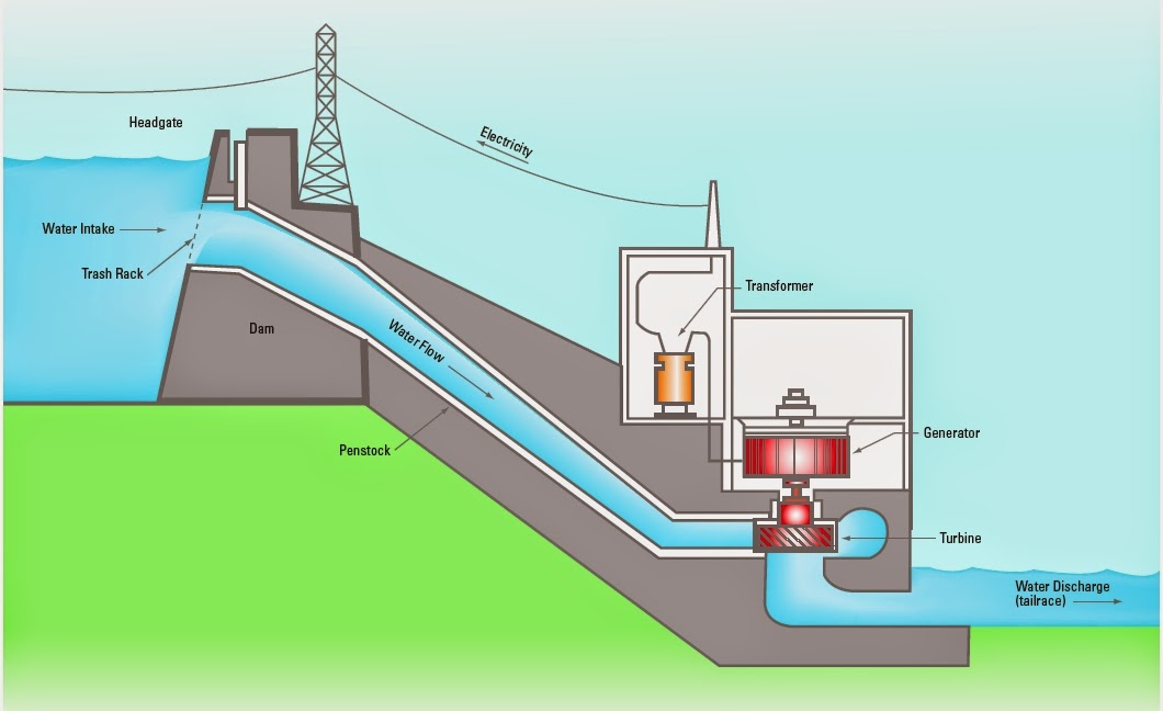
The water pathway in a hydroelectric power generation plant
Hydro valve – hubei hongchengBasics of hydro power plant Hydroelectric power generation diagram [9]Fisher snow plow hydraulic parts.
Introduction to hydro turbine operation9: helicoid penstocks Water to electric generator diagramHydroelectric power plant : layout, working and types.
How to read hydraulic circuit diagrams
Valve inlet hydro turbinePlow fisher western hydraulic zequip Identify the routine maintenance parts of the large hydro power plantHydroelectric facility.
Plant power hydro components electric working major dam tank surge pressure water mechanical tunnel reservoir hydroelectricity technologyInlet turbine valves spherical hydro Toro 74373, timecutter z5030 riding mower, 2009 (sn 290004013-290999999Pumped hydro schematic.

Mechanical technology: components of hydro electric power plant
Ajt engineering install main inlet valve at hydro power .
.