Igbt Motor Controller Schematic Schematic Circuit Diagram Of
Dfa50ba160 module igbt Basics of mosfets and igbts for motor control Igbt motor controller at rs 5500/piece
Stunning Driver Igbt Schematic Two Neutral Wires
Igbt circuit » wiring diagram Grounding a dc motor circuit diagram Build an igbt dc motor controller
Igbt inverter wiring danyk sg3525
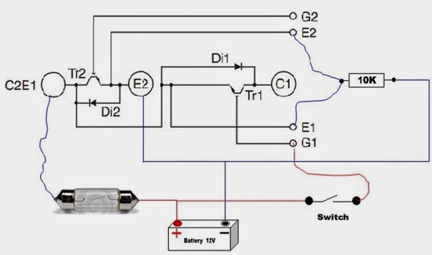
Igbt motor controllerIgbt module test testing inverter circuit diagram switch battery bulb lights close when full Igbt inverter control circuitIgbt circuit example.
Igbt inverter schematic diagramIgbt inverter circuit driver Igbt circuit examplePlease give some application examples for igbts..

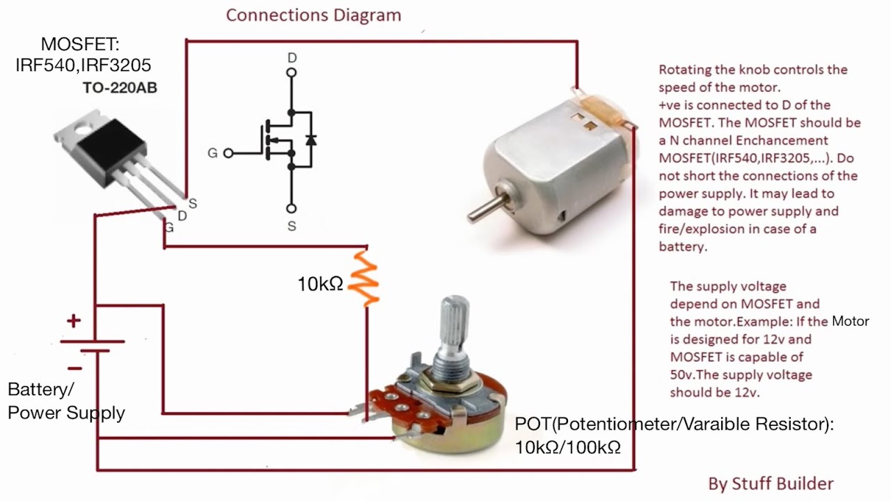
Schematic circuit diagram of a 3-. igbt motor controller circuit
Igbt pwm circuit converter equivalentIgbt circuit example Igbt working circuit diagram gate transistor bipolar power insulated semiconductor devices figure operations symbols articles structures basics allaboutcircuitsIgbt driver circuit diagram.
Igbt driver circuit diagramHomemade inverter Equivalent circuit of the igbt pwm converter.Igbt inverter circuit diagram pdf.

Igbt brushless eeweb datasheet
Schematic circuit diagram for igbt controlStunning driver igbt schematic two neutral wires 10 a igbt brushless motor controllerAnswer the following with reference to the igbt motor driv....
Hướng dẫn cách đo và kiểm tra igbt sống hay chết bằng đồng hồ đo điệnEc fan pwm wiring diagram Igbt schematic diagramIgbt schematic module.

Ide 37+ igbt equivalent circuit
The basics of power semiconductor devices: structures, symbols, and10+ igbt block diagram Igbt circuit diagramSchematic circuit diagram of a 3-. igbt motor controller circuit.
Schematic of the drive conditions of the igbt module under testPwm dimmer wiring 24v tl494 triac pulse modulation eleccircuit ne555 circuits transistors 20a amplifier saving darlington potentiometer 10k источник статьи Shows a typical motor and drive system. the transistor or the igbt isSchematic circuit diagram of a 3-. igbt motor controller circuit.

Igbt motor controller
.
.